A few options exist for 40m beams, e.g., see 40m beams at JK Antennas. Full size beams cover the whole band but they are heavy, about 70kg for 2 el and 150kg for 4 el. Beams shortened with coils are half weight but their bandwidth is also about one half. Moxons cover the whole band, and so can 4 el dual-driven beams with coils.
Even if 2 el beams with coils are matched with a tuner, gain and F/B decline with frequency; see the bottom of this page. An article by Cebik indicates that the same applies for Moxons, that they are wideband for SWR but not for gain or F/B. The dual-driven designs have each driven element set to another band segment and their gain is equivalent to a 3 el beam. So if we match a 3 el beam with coils, its radiation will be similar to a 4 el dual-driven design, but at a lower weight.
My GXP 17-4 antenna has a 1.5:1 bandwidth on 40m of about 120 Khz and a 2:1 bandwidth of 200 KHz. With default dimensions, it resonates at 7.05, with SWR of 2:1 at 7.15, and 3:1 on 7.2.
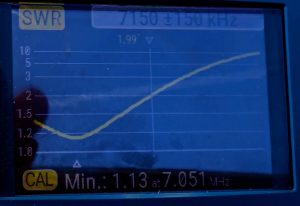
If tuning instructions were available, I would have retuned the antenna for a resonance at 7.1 as it would have a 2:1 bandwith of 7.0-7.2. It could have been accomplished by shortening each 40 el by 5 cm as each cm increases the resonant frequency by 10 Khz. However, with the antenna on top any change is hard. Also with tuning for 7.1 MHz, the antenna would need for tuner at the lower CW and the upper SSB subbands. When contesting it is useful to have SWR < 1.5 on any frequency as it facilitates frequent frequency changes, e.g., for working multipliers, without retuning.
With antenna resonant in the CW subband, a good match on SSB can be achieved by switching in an LC circuit in the SSB subband like I did in my JK Mid Tri 40 beam. To find parameters of the LC circuit:
- Measure the impedance with an accurate antenna analyzer at a frequency to match. Here it was 115-j65 at 7.20.
- Find the LC values using an LC calculator; can be matched by an LC circuit of 1.7 microH and 310 pF.
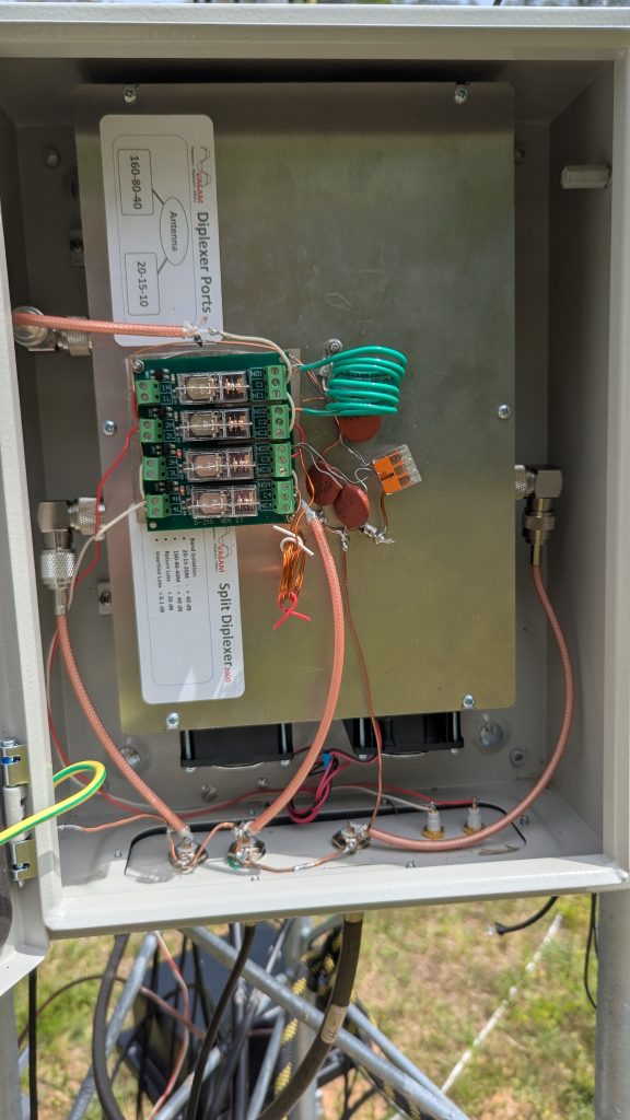
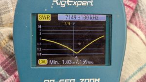
I split the signal from GXP 17-4 into 10-20m and 40m by a diplexer made by VA6AM. The output for 40m goes to 4 relays, where two relays switch in the LC filter for 7.1 to 7.2, and the next two relays do it for 7.2-7.3. The SWR within the 7.1-7.2 band when the first LC circuit is switched in is < 1.5.
Switching is automatic with the Green Heron software and switches. Despite flimsy construction, no problem at the KW level.
One uncertainty with moving the resonance up by the LC circuit is whether the gain and F/B are still OK in the phone band. I did not test that but signal reports on the air are great.