Once the GXP antennas were up,
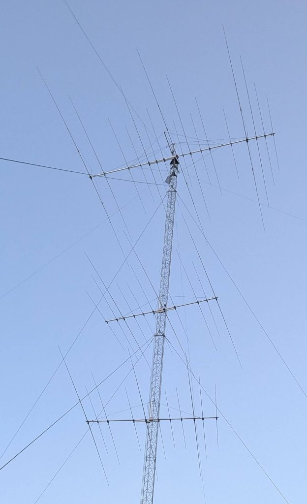
there was time to test the SWR curves.
![]()
20 and 10m were fine but in all antennas the resonance on 15m was too high, with SWR at 21.00 MHz > 2:1.
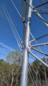
The 15m element was too short and needed to be extended by about 10 cm.With the boom screws loosened, the 11-3 antennas could be rotated on one side only as the transmission line was hitting the other way.
I extended only one side of the driven element by 10cm for both 11-4, and now the SWR curve was fine.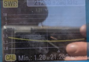
I wanted to do the same for the 17-4 antenna on top, but its horizontal guys limited the rotation. To rotate, one would have to temporarily remove the guys, not an easy job. But a call from SP7GXP pointed to a much simpler solution: unscrew the 15m driven element at a point closest to the boom, adjust, and put it back. I
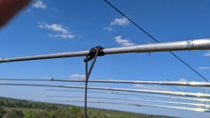
It was easy.
The 17-4 antenna has a narrow bandwidth on 40m. While it is low in the CW band, it is 2:1 at 7.15, and 3:1 on 7.2. Two solutions exist. One is to shorten the driven element to move resonance to 7.1. Then, 7.00–7.20 would be covered with SWR < 2:1.
The GXP documentation showed only a single setting for 40m that turned to be for CW with a resonance at 7.04. A documentation for another GXP antenna indicated that shortening all 40m elements by 1 cm increases the resonant frequency by 10 KHz. So all 40m elements should have been 6-8 cm shorter.
While changing the elements in the air is next to impossible, the other solution is to switch in an LC circuit in the SSB subband like I did in my JK Mid Tri 40 beam.