Once the GXP antennas were up,
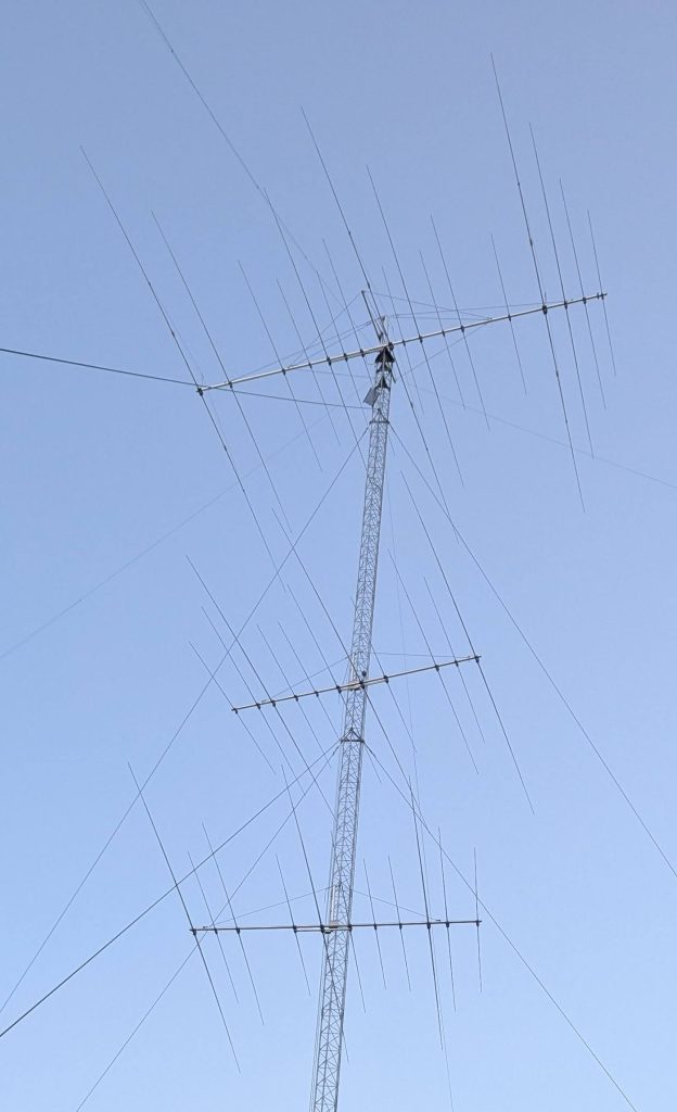
there was time to test the SWR curves.
![]()
20 and 10m were fine but in all antennas the resonance on 15m was too high, with SWR at 21.00 MHz > 2:1.
The 15m element was too short and needed to be extended by about 10 cm.With the boom screws loosened, the antenna could be rotated on one side only as the transmission line was hitting the other the other way.
I extended only one side of the driven element by 10cm for both 11-4, and now the SWR curve was fine.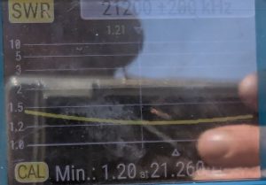
I wanted to do the same for the 17-4 antenna on top, but its horizontal guys limited the rotation. To rotate, one would have to temporarily remove the guys, not an easy job. But a call from SP7GXP pointed to a very simple solution: unscrew the 15m driven element at a point closest to the boom, adjust, and put it back.
Another problem is a narrow bandwidth of the 17-4 antenna on 40m. While it is low in the CW band, it is 2:1 at 7.15, and 3:1 on 7.2. Two solutions exist. One is to shorten the driven element to move resonance to 7.1. Then, 7.00–7.20 would be covered with SWR < 2:1. The other solution is to switch in an LC circuit in the SSB portion like I have in my JK Mid Tri 490 beam. On 7.2, the impedance of 115-j65 can be matched by an L circuit with a coil of 1.5 microH and a cap of 320 pF. Switching can be made automatic with the Green Heron software and switches.